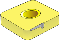
If you don't know much about insert failure and its negative impact on your manufacturing equipment, it's similar to an athlete exhausting a good pair of running shoes. Much like a shoe under the weight of the runner wearing it, an insert endures tremendous stress over and over again; creating wear and tear. If not addressed, wear can cause pain for an athlete and inaccurate processes or poor productivity for a manufacturer.
Manufacturers, however, can analyze their used tooling to achieve maximum tool life and predict tool usage; thereby maintaining part accuracies and reducing equipment deterioration. By understanding the various mechanisms (listed below) that contribute to insert failure, you can take the appropriate course of action to ensure optimal cutting performance at all times.
Flank Wear
Normal flank wear, which occurs uniformly, is the most predictable of all failure mechanisms because it is largely due to normal abrasion. Similar to a jackknife blade that dulls over time, flank wear happens over time as the work material wears the cutting edge.
Rapid flank wear, on the other hand, happens faster, especially when cutting abrasive materials, such as ductile irons, silicon-aluminum alloys, high temp alloys, heat-treated PH stainless steels, beryllium copper alloy and tungsten carbide alloys, as well as non-metallic materials, such as fiberglass, epoxy, reinforced plastics and ceramic.
You can reduce rapid flank wear by lowering your cutting speeds or, better yet, using a more wear resistant, harder or coated carbide grade.
Cratering
Cratering is a heat/chemical problem that often occurs when machining iron or titanium-based alloys because the tool dissolves into the workpiece chips.
You can avoid cratering by using a coated grade (preferably coatings with aluminum oxide), applying coolant, utilizing a freer cutting geometry to reduce heat, increasing lead angle, and reducing cutting speeds and feeds. The last corrective action can be counter-productive so it should only be used as a last resort.
Built-up Edge
Built-up edge occurs when fragments of the workpiece are pressure-welded to the cutting edge. This failure mechanism commonly occurs with gummy materials, low speeds, high-temperature alloys, stainless steels and nonferrous materials, and threading and drilling operations.
You can control built-up edge by increasing cutting speeds and feeds, using nitride (TiN) coated inserts, applying coolant, and selecting inserts with force-reducing geometries and/or smoother surfaces.
Chipping
Chipping originates from mechanical instability often created by non-rigid setups, bad bearings or worn spindles, hard spots in work materials, or powder metallurgical (PM) materials.
You can deter chipping by ensuring proper machine tool set up, minimizing deflection, using honed inserts, controlling built-up edge, and employing tougher insert grades and/or stronger cutting-edge geometries.
Thermal Mechanical Failure
A combination of rapid temperature fluctuations and mechanical shock can cause thermal mechanical failure. It is most often experienced in milling and interrupted-cut turning, facing operations on a large number of parts, and operations with intermittent coolant flow.
You can prevent thermal mechanical failure by applying coolant correctly or, better yet, removing it from the process completely, employing a more shock-resistant grade, and using a heat-reducing geometry.
Edge Deformation
Heat and pressure are two sources of edge deformation, which commonly occurs with high-heat operations, high speeds and feeds, or machining hard steels, work-hardened surfaces and high-temperature alloys.
You can control edge deformation by applying coolant, using a more wear-resistant grade with a lower binder content, reducing speeds and feeds, and employing a force-reducing geometry.
Notching
Notching happens when there is a difference in hardness or abrasiveness within a workpiece. It often occurs in materials with surface scale or oxidation as well as work-hardened, cast and irregular surfaces.
You can control notching by varying the depth of cut when using multiple passes, using a tool with a larger lead angle, increasing cutting speeds when machining high-temperature alloys, reducing feedrates, carefully increasing the hone in the depth-of-cut area, and preventing build-up, especially in stainless steel and high-temperature alloys.
Mechanical Fracturing
Mechanical fracturing occurs with any kind of excessive wear. Therefore, when the mechanical load is great enough, the insert breaks during the first moments of a cut.
You can avoid mechanical fracturing by correcting all other failure mechanisms besides normal flank wear, utilizing a more shock-resistant grade, selecting a stronger insert geometry, using a thicker insert, and reducing feedrates and/or depth of cut.
If your shop is experiencing insert wear, Seco can help. We have a wide variety of insert geometries, grades and coatings from which to choose, including our exclusive Duratomic coatings that improve toughness and wear resistance by altering the crystal structure at the atomic level. And if you?re not exactly sure how to maximize your operations, our team of metalworking experts can evaluate your processes and determine the best possible solutions for your needs.
About the Author
 Don is the manager of education and technical Services for Seco, responsible for all educational activities for the NAFTA market, new product testing and various other technical functions. Outside of work, he enjoys making maple syrup, restoring antique tractors and farming. Don can be reached at dgraham@secotools.com.


