Friday, February 1, 2013

HFM Strategy Benefits Medical Customer – What About You?


By Eric Gardner, Medical Segment Specialist

We work with customers from a variety of industry segments, including aerospace, automotive, energy, oil and gas and medical, and assist them in determining the best possible solution for optimizing their unique applications.

One highly successful project that comes to mind was helping a company improve the milling of its orthopaedic knee replacement components made from cobalt chrome (Co-Cr). While this material has great biocompatibility, meaning it works well in the human body, it’s tough stuff that can be the bane of many machinists. 

Before we got involved, the company was struggling with tool life, averaging one conventional solid carbide end mill for every six parts. Add in the time required to change tools, process disruption and the perishable tooling cost per part was approximately $5 per workpiece. 

We suggested the company apply high-feed milling (HFM) techniques using a high-performance high-feed milling tool as opposed to a conventional end mill. In doing so, the company brought its tooling cost per part down to around $2, without impacting production time. And perhaps the greatest benefit was increased process stability and predictability, which led to less scrap and higher quality machined products.

While a high-performance high-feed milling tool may cost a lot more upfront than a standard cutter, you can reduce your tooling costs substantially over the long haul by making the switch. That’s because there’s more to high-feed machining than cranking up the feedrate, and high-quality tools play a big role in successful high-feed milling. 

Commodity end mills can’t handle high-feed milling requirements, namely extreme chips loads and the associated heat, pressure and cutting forces generated when flying through a workpiece at feedrates up to 10 times faster than seen with conventional machining techniques.      

The high-feed milling tools we recommended to the company were made from a tough grade of micro-grain carbide and coated with a heat and wear-resistant TiAln coating. The geometry of the cutters involved shallow flutes with a neutral rake and very slow helix. And unlike general-purpose end mills, which typically have a square profile and zero-radius edge, our high-feed milling end mills have rounded ends, with corner radii upwards of 25% of the tool diameter. All of these features make for a tough cutting tool, one of which can withstand far higher feedrates in Co-Cr than less robust solutions.  

Tips for Putting High-Feed Milling to Work for You

Seco High-Performance High-Feed Milling Solutions
Compared to conventional machining, where a relatively large depth of cut and lighter feedrate is the norm, high-feed milling relies on heavy chip loads and shallow depths of cut. You might be skeptical, but high-feed milling works because most of the cutting forces generated are directed axially, perpendicular to the cut and up into the spindle, which creates greater tool stability and reduces vibration, both of which increase tool life. Also, the smaller chip tends to carry the heat away from the cut, further increasing tool life and, in many cases, allowing for higher metal removal rates. 

In high-feed milling, because the cutting tool is cruising along at such a high rate of speed, you have to pay special attention to your tool path. Constant cutter engagement is critical, which means you have to remove metal in a predictable and consistent manner. You can’t let your tool stall in the corner or you’ll rub it to death, and if you come into a corner that has the same radius as your cutter, all of a sudden your cutter engagement goes through the roof and you’ll break the tool every time. And you need to know how much material is in front of you at all times – when you’re driving a tool this fast, any speed bumps or potholes in the road can mean a broken tool. 

All of this might be difficult to achieve using “traditional” or outdated programming systems, but there are several good CAM programs out there with high-feed milling in mind. Look for the ability to ramp in and out of the workpiece, so as to avoid shock to the tool. Trochoidal and helical milling paths, corner rounding capability and smooth 3-D contouring – all are valuable assets in the high-feed milling toolkit, ones which reduce sharp angular changes in the tool path while still providing constant cutter loads, thus minimizing adverse cutting impacts and extending tool life.

However, the best tool path and the best cutter will fail without a good machine tool. Because high-feed milling moves the tool rapidly down the proper tool path – one that maintains constant cutter engagement and avoids shock to the cutter – you need several things to support this. One of the primary requirements for any CNC machine tool is rigidity, which means high-quality guideways, rigid construction, and proper installation and environment. And since so much of the cutting force during high-feed milling is directed upwards in the Z-axis, you need a spindle of sound design and construction that can absorb those forces, preferably one fitted for HSK or dual-contact toolholders. 

Also necessary is a modern machine tool control, especially for machining complex 3-D shapes. 3-D contouring of any kind generates massive amounts of data, and only those CNC controllers with high-speed processors and extensive look-ahead capabilities can keep up with these demands. And to serve the commands of the CNC quickly and accurately, the servo systems must be robust as well, and be able to maintain smooth and continuous motion even when traveling several hundred inches per minute as is frequently seen in high-feed milling. 

In Closing

High-feed milling is a complex strategy and the above tips are just a starting point. Speeds, feeds and setup techniques are some other things to think about. Just know that if you have questions or need assistance with a high-feed milling strategy, please don’t hesitate to contact us. Our expertise runs deep so whether you are in the aerospace, automotive, energy, medical or oil and gas industry, we can help optimize your process. 

About the Author
As medical segment specialist, Eric provides technical sales and marketing support to Seco’s medical manufacturing customers. In his spare time, he enjoys spending time with his daughter as well as shooting sporting clays. Contact Eric at egardner@secotools.com.

Wednesday, January 30, 2013

My Own Kind of Networking

Special Guest Blog by Mark Albert, Editor-in-Chief, Modern Machine Shop

Networking is an activity that is hard to define. It’s more purposeful than hobnobbing; more sincere than schmoozing. Meeting new people who can do things with you or for you to mutually benefit from, is networking at its best. Doing this kind of networking is one of the reasons why I attended “Making Manufacturing a Priority,” this year’s inaugural event for the committee that directs “Automation Alley,” a long-standing government/industry initiative, which seeks to boost manufacturing in southeastern Michigan.
Kurt Nordlund, president of Seco Tools NAFTA,
welcoming people to the event.
Hosted by Seco Tools at its North American headquarters and technical Center in Troy, Michigan, this event drew more than 100 attendees representing a variety of manufacturing companies from the region. Speakers, roundtable discussions, several tabletop exhibits and machine tools running in the showroom comprised the “program” for this late afternoon-early evening event and gave it just enough structure for lively yet focused participation. There was also plenty of time for networking, which, according to Seco, provides a commercial-free forum for manufacturers and their suppliers to meet and discuss topics important to them.

Here are a few examples of the networking contacts that I made at the “Making Manufacturing a Priority” event sponsored by Seco Tools in Troy, Michigan on January 8, 2013 for Automation Alley.

Don Graham is Seco’s manager of education and technical services. He told me about some new materials and new processes that Seco is investigating. One of these new materials promises to greatly decrease the weight of components used in the “hot section” of a jet engine. The material, however, is one of the most difficult materials to machine Seco has ever encountered, so it is a real challenge to a cutting tool developer. One of the new processes is laser-assisted machining, in which preheating the workpiece material with a laser just in front of the cutting tool presents interesting new possibilities for metal removal strategies.
Likewise, Tim Aydt and Don Halas, two Seco product managers, shared some innovations they’ve been working on. For example, Tim (a turning specialist) talked about how insert coatings developed for milling applications are proving valuable for turning inserts, enabling one insert grade to turn workpieces with a hard outer layer and a softer core underneath. Don (a threading and grooving expert) told me about changes in the exploration for natural gas that are putting cutting tools developed for aerospace into oilfield applications to cut special thread forms. It seems that strongly acidic conditions deep underground require the kind of alloys (and machining processes) normally used on aircraft components and jet engines.
Later, near the beverage bar, I met Don Jasurda, whom I met years ago when Don was with a CAD/CAM company. Don is now VP of Sales for Dimensional Control Systems, Inc., in Troy. This company provides metrology optimization services for large manufacturing companies. In addition to renewing our acquaintance, we discussed his company’s plans to make its technology available to smaller manufacturing companies and job shops. I promised to get the news out when the new products are launched because the underlying concepts put advanced metrology in a fresh perspective.
In the break room where a hot buffet was being served, I sat down with Gary and Lisa Seidl. Lisa is Seco’s marketing communications manager. Gary’s employer, Quick-Built, makes automated machinery for inserting metal components into plastic parts as they come off the injection machine. He and I chatted about how customers in the local area are carefully managing the mix of automotive and not-automotive work.
At the end of the evening, I sat down with Mike Parker and Bob Goulding, two more Seco guys. Mike is Director of Engineering, Marketing & Product Development, while Bob heads Seco’s Component Engineered Tooling group. Bob’s enthusiasm for this part of Seco’s service to manufacturers was effervescent. His group develops entire manufacturing processes (equipment selection, machining parameters, cutting tool strategies, CNC programming and so on) for customers. He was quite proud of some remarkable successes his group has created recently for leading manufacturers in the Detroit area and around the country. I was unaware that Seco provided the service. After listening to Bob, I’d like to develop some case histories about these success stories.
My notes and additional collection of business cards from this event are further evidence of effective networking (for me!). If other attendees were equally effective at networking, we can safely declare “Mission Accomplished” for Automation Alley’s 2013 inaugural event.

View Mark Albert's original blog post on mmsonline.com. 

About the Author
Mark Albert is editor-in-chief of Modern Machine Shop Magazine, a position he has held since July 2000. He was associate editor and then executive editor of the magazine in prior years. Mark has been writing about metalworking for more than 30 years. Currently, his favorite topics are lean manufacturing and global competitiveness. Mark’s editorial activities have taken him to numerous countries in Europe and Asia as well as across the United States many times. He is a graduate of the University of Cincinnati (Cincinnati, Ohio) and Indiana University (Bloomington, Indiana).

Friday, January 4, 2013

Diamond-Tip Technology Advances Holemaking in Composites


By Scott Turner, Drilling Manager

New CX1 and CX2 Solid PCD-Tipped Drills
Next month, we’ll put a new spin on drilling through composite materials with the launch of our new CX1 and CX2 solid PCD-tipped drills. While traditional PCD and diamond-coated drill designs can sometimes fall short in composite drilling applications, these two new solutions prevent delamination and uncut fibers like never before.  

With bodies made of solid carbide, the CX1 and CX2 drills feature a solid PCD dome and solid PCD cap, respectively, as opposed to the more common PCD vein or dual brazed tip designs. Furthermore, our new PCD technology made it possible for us to develop the industry’s first PCD three-flute geometry (CX1) for composite drilling. 

The CX1 and CX2 PCD drills offer the sharpest and strongest cutting edges currently available, providing you with the best possible hole quality and a significant reduction in machining time. This performance is possible because these new drills use solid PCD tips that are much sharper than PCD-coated drills where the coatings wrap around a drill’s cutting edges and actually create a dulling effect.

CX1 Geometry
CX1 Geometry Features and Benefits

• Third flute provides high levels of stability in the hole as well as decreases vibrations and improves roundness.

• Dome-shaped tip applies a double-angle geometry that reduces uncut fibers and delamination in composite-only applications. The tip also makes it possible to recondition the drill point.

• Solid PCD tip lowers process temperatures to enhance product stability and allow for higher cutting speeds.

• Available in a variety of dimensions for holes that range in size from 0.125” to 0.375”. Chamfers can also further increase application flexibility.

CX2 Geometry
CX2 Geometry Features and Benefits

• Flat geometry drill point ideal for machining stacked composite materials with layers of aluminum, titanium or stainless steel.

• PCD cap supports 180-degree drill point angle that provides efficient chip breaking and evacuation qualities. This reduces the chance of metal chips damaging the hole when transitioning between layers of metal and composites.

• Solid PCD tip lowers process temperatures to enhance product stability and allow for higher cutting speeds.

• Available in a variety of dimensions for holes that range in size from 0.125” to 0.375”. Chamfers can also further increase application flexibility.

Solid PCD-Tipped Drills Versus PCD-Coated Drills

While solid PCD-tipped drills are more expensive than PCD-coated drills at the front end, the overall return on investment for solid-tip designs is substantial if you are drilling a large number of holes and essentially spreading out the cost of each hole. In fact, the PCD drills with the CX1 and CX2 geometries have the ability to effectively drill two to three times more holes than a PCD-coated drill.

Investing in solid PCD-tipped drills also makes sense when hole quality is of the utmost importance. However, if you have an application that is not part of a continuous running process and hole quality is not as critical, PCD-coated drills would prove more cost effective.

It is also important to keep in mind that rigid setups are necessary when machining composite materials. After all, composite materials are typically thin and, therefore, require more support. Without the right setup, you run the risk of frequent drill breakage and hole quality compromise. Therefore, in less rigid setups, a PCD-coated drill would make the most economical sense.     

In composite drilling applications, the use of portable drills is common. As such, both solid PCD-tipped drills and PCD-coated drills can prove effective; however, there needs to be enough RPM range to optimize the application. Therefore, in situations where there is not enough RPM, a solid PCD-tipped drill would be the better choice. After all, PCD-tipped drills work best in optimally run applications where more productivity and improved hole quality is a must. 

We consider the CX1 and CX2 to currently be the most advanced solutions for drilling today’s challenging composite materials. And given that every composite-based operation varies, we now have the technology to make special PCD geometries if so required. And as composite materials continue to evolve, we will constantly work to advance our drill designs to provide the best possible hole quality, productivity and profitability.

About the Author
As drilling manager, Scott is responsible for the product development, applications support and marketing of advanced hole-making solutions. In his spare time, he enjoys participating in outdoor activities such as jet skiing, snow skiing and golfing. Contact Scott at swturner@secotools.com. 

Friday, December 14, 2012

Six Reasons Thread Milling is Better Than Tapping


By Bob Winegard, Application Support and Training

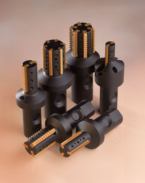
Thread milling surfaced approximately 25 years ago in response to NASA’s need to machine high-quality threaded holes in extremely tough materials such as titanium, Hastelloy and Inconel – a feat not possible with a tap. Over the years, thread milling has and continues to evolve, and manufacturers are now using the process to produce strong, exceptional threads in hardened materials up to 70 Rockwell.

Top six reasons thread milling is better than tapping:

1.  You’ll always achieve a better thread quality with thread milling than tapping.

2.   Depending on your hole size, you can perform tapping either by hand or machine. With thread milling, however, you must always use a machine, which ensures better overall thread consistency. 

3.  Thread milling is a lot easier on your machine tool because it requires much lower cutting forces than tapping.

4. In thread milling, you don’t have to have the hole right on size because the thread mill will cut the hole larger. When people tap, they typically tap the hole larger than necessary because it is easier. However, in doing so, they lose part of the thread and reduce its overall strength.

5. It’s common for smaller taps to break during the tapping process. Upon breaking, you can try to get the tap out of the hole, which can be time consuming, but more often than not, you will need to scrap your part.    

6.  With thread mills, you can create right and left-handed threads using the same tooling.


Keep in mind, however, before you can thread mill you must have a machine tool with three-axis capabilities. While most of today’s machines have such abilities, a lot of older equipment does not. You must also consider how deep you need to thread mill because you should not go deeper than one and a half times the diameter of your hole. The reason being is that the longer your milling tool, the more chance you have of experiencing deflection, which can create inaccuracies in the thread.

With thread milling, you have a couple of tooling options from which to choose. You can opt for either a solid carbide or indexable tool. Solid carbide tools are ideal for smaller hole sizes because an indexable tool typically won’t fit in holes that are ⅝” or less in diameter. In terms of cost, solid carbide thread mills are more expensive than indexable designs. With an indexable tool, once you've purchased the thread mill body, the cost of the inserts are more affordable than solid tooling. Indexable tools also have shanks made of steel, which makes them more forgiving than solid carbide tools.     

Lastly, before you go to thread mill, be sure to take advantage of Seco’s Thread Milling Wizard software, which is available via our web site. The software will ask you a series of questions about the type of thread you’re trying to achieve, and based on your responses, it will create a highly effective, tailor-made CNC program for use with your machine tool.

About the Author  
As an integral member of Seco’s dedicated application support and training team, Bob works closely with Seco customers to help them optimize their tool usage and find ways to increase their productivity and reduce costs. Contact Bob at bwinegard@secotools.com.