Thursday, January 28, 2016

How to Best Deal With (Part) Rejection

By Todd Miller, Manager of Product Marketing

No one likes rejection, especially in the world of parts production. Manufacturers running critical applications know there’s nothing worse than having to scrap expensive, time-consuming components because of burrs or unacceptable edge conditions. Sound familiar? Then it might be time for you to tackle these unsightly manufacturing blemishes differently.

Mechanized Edge Profiling, or MEP, could be your answer, especially if you’re deburring components using hand grinders or other manual processes. Because, even when performed by skilled craftsmen, manual techniques are slow and lack the required process consistency from part to part.

MEP, however, is a controlled strategy involving precision engineered tools, guided by a machine tool’s CAM program, to remove burrs and sharp edges quickly and consistently. It’s also a documentable method that can increase your repeatability and reduce your setup and part handling expenses.

Before implementing MEP, it’s important to make sure you have the right tools for the job. When machining non-rotating components, such as aircraft engine casings, it’s best to use solid-carbide chamfering end mills and edge-break tooling. However, when profiling edges on contouring components, ball nose and lollipop-style tools are your best bet.

Custom MEP tooling is necessary when cutting critical rotating parts that require perfect surfaces, such as aircraft engine fans. These special tools have specific radii, chamfers and angles that are essential to machining flawless, lab-certified edge profiles. The most sophisticated deburring tools have edge designs that produce a chamfer with a radiused edge preceded by lead-in and lead-out angles to prevent formation of secondary burrs.

When putting MEP into action, you should use it as a portion of the actual part feature machining operation for maximum accuracy, consistency and productivity. Deburring should occur after all machining operations are completed. The CAM program directs the MEP tools to deburr all the holes and break sharp edges in sequence. Some MEP tools can be used to deburr a variety of holes, and some profiling tools can be applied on three or four different locations or features, such as the bottom of a hole as well as the bottom of a scallop contour.

To ensure that the edge profiling takes place in the correct location and with the proper amount, your part’s hole or feature must be defined or measured before the MEP operation begins. When part tolerances are very tight, the location of the part surface should be well defined and in-process measurement may be unnecessary. However, if the location is in question, measurement will be necessary after initial machining to determine the location of the edge or feature to be profiled.

In addition, the tool itself must be measured and located to ensure that it will profile the part correctly. Because the tool radii are so small — and for practical purposes, unmeasurable — the tool length is specified in the CAM program. You can confirm the tool length away from the machine with a presetter or on the machine via a laser or touch probe. Feed rates are calculated relative to the measured dimensions of the part features and the tool.

Overall, you should consider the deburring or chamfering process as a finishing pass, with your primary focus on quality. Productivity is always important, but especially in the case of expensive components, pushing the tool to maximize output can have negative, and costly, repercussions. Consistency, reliability and elimination of scrap parts are paramount because no one likes the feeling of rejection.

If you have questions about MEP, please don’t hesitate to contact me or our technical support team. You might also want to check out the published Seco technical article “How MEP Takes the Edge Off Parts Manufacturing.”

About the Author
Todd oversees the product marketing team at Seco Tools LLC. and works with the company’s sales department to further enhance the customer experience. He and his team also support product introductions while working globally on new product testing to ensure customers gain access to the industry’s most advanced tooling as quickly as possible. In his spare time, Todd likes to go bowling as well as cheer on the University of Michigan football team.

Thursday, January 14, 2016

Take the Load Off Your Turning Tools

By Chad Miller, Product Manager – Turning and Advanced Materials

Do you find yourself frequently frustrated by premature tool deterioration or failure during turning operations? Understanding the four basic types of machining loads and how each affects your cutting tools can help you achieve slow, predictable tool deterioration as well as increase productivity and profitability.


The four load types are: mechanical, thermal, chemical, and tribological, and each one contributes to the wear and failure of your cutting tool. You’ll find these loads do not act independently, but rather interact and influence the sum of their effects on tool deterioration.
  • Mechanical loads in turning are steady; however, any interrupted cuts during the process produces impact loads that can chip or break the tool. 
  • Thermal loads occur when workpiece deformation generates heat up to 1,650 degrees Fahrenheit, causing tool deformation and blunting. 
  • Chemical loads occur when heat and pressure combine between the cutting and workpiece materials, producing tool wear in the form of diffusion or cratering.
  • Tribological loads happen when there is friction between the tool and chip, creating abrasion and erosion-type wear.
You can, however, mitigate the negative impact these loads have on your tools using two strategies.

Strategy 1:


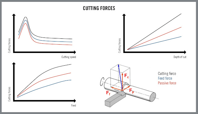
Manipulating your cutting parameters can influence the level of load impact on your tool. Keep in mind, however, depth of cut, feed and speed all have differing effects on machining loads, so you should consider the following:
  • Doubling the depth of cut doubles the cutting force but also doubles the length of the cutting edge in cut. This results in the load remaining the same per unit of cutting edge length.
  • Increasing feed rate increases cutting forces, but to a lesser, non-linear degree. Because the greater feed increases chip thickness, not the length of the tool in the cut, loads are seriously increased on the cutting edge.
  • When increasing cutting speed, forces generally remain the same, but power requirements rise.
  • Cutting forces rise at lower cutting speeds and decrease at higher cutting speeds. Watch closely for a built-up edge, which may indicate inappropriate cutting speed.
  • Too high of cutting speeds can reduce the reliability of a process through uncontrolled chip formation, extreme tool wear and vibration that can make a tool chip or fracture.
  • Higher feeds and depths of cut combined with low or moderate cutting speeds offer the best potential for operational security and reliability. Higher cutting speeds, if depth of cut and feed are sufficiently low to limit cutting forces, can provide greater productivity.

Strategy 2:


The basic size and shape of a tool determines its strength and capabilities. Often times, tool geometries are engineered with a specific application or workpiece material in mind. So, it's critical to have the best tool for the job right from the start. Here are a few things to keep in mind when selecting tools:
  • A large, strong insert enables use of highly productive feeds and depths of cut because cutting forces acting on a large insert will result in lighter loads than the same forces would create on a smaller insert.
  • A round insert shape is the strongest, and a 90-degree corner of a square insert is stronger than a 35-degree corner of a diamond insert. However, a round insert cannot cut the same variety of part profiles as a 35-degree tool. There is a tradeoff of strength for flexibility of application.
  • Generally, the best tool for cutting steel, where toughness is required, has a honed edge. The best tool for cutting stainless steel, which tends to be gummy, has a sharp edge.
  • Very sharp cutting edges may not necessarily provide the best surface finish. The best results often are obtained after an edge has run for a period of time.
Tool deterioration during machining is inevitable, but as you can see there are ways to slow the process and better predict when a tool will fail. Metal cutting is definitely a complex process, so any time you have questions or require applications advice, please don’t hesitate to contact me or our technical support team.

Read the published Seco technical article “Mechanical Loads and Cutting Geometries in Turning Operations.”

About the Author
Chad manages Seco's turning and advanced materials product lines, including all CBN and PCD products. When he's not helping customers implement advanced metal cutting solutions, you can find him training for and running 5K, 10K and 1/2 marathon races and triathlons.